подвеска Трофи Трака, как ?
Модератор: User buggy
-

McFly
- Младший юзер
- Сообщения: 13
- Зарегистрирован: Пт дек 18, 2015 5:27 pm
подвеска Трофи Трака, как ?
Всегда поражает физика работы подвески таких машин! Таких на дорогах и родине нет! Уверен, что впечатления от «покататься» сверхъестественные! Понятно, что в поворотах клонит, но прохождение ухаб -все эмоции перерождает! Итого вопрос: в чем секрет такой подвески, особенно задней?
Никто в РФ на пребывал из подручным материалов собрать такое?


-

Андрей 318
- Познавший Истину
- Сообщения: 2790
- Зарегистрирован: Чт авг 20, 2009 9:31 pm

Re: подвеска Трофи Трака, как ?
Сообщение
Андрей 318 » Пт май 27, 2016 3:09 pm
McFly писал(а): Итого вопрос: в чем секрет такой подвески, особенно задней?
Никто в РФ на пребывал из подручным материалов собрать такое?
Секрет в геометрии и в хороших (очень дорогих) упругих элементах.
На данном форуме полно аналогичных схем подвески, но упругие элементы сделаны из того, что есть под рукой.
-
X-Centric
- Студент
- Сообщения: 72
- Зарегистрирован: Ср сен 30, 2015 8:31 pm
Re: подвеска Трофи Трака, как ?
Сообщение
X-Centric » Пт май 27, 2016 3:37 pm
Не могу понять, а схема задней подвески у полариса РЗР или как тут у Арктик Кат- это нечно среднее между трехрычажки и классическими а-образными? Получается полностью убрать подруливание из-за продольного рычага? Он на шарнире? А то пробовал подобное моделировать, так у меня задние колёса так в разные стороны разъезжались, что страшно становилось. Подумалось, что такая подвеска только с очень длинным продольным рычагом и малых ходах имеет право на жизнь. А тут видяшки с РЗР смотрел, так там ход в районе 300-350, и ничё, спокойно так и прыгают и по буеракам со скоростью овер 100 гоняют. Пояснит может кто? Так то такой вариант- хороший выход при дефиците места сзади вместо а-образных поперечных, если ходов хочется. А то давно пытался что-то такое моделировать, но без подруливания никак.
-
Vitalya32
- Познавший Истину
- Сообщения: 2080
- Зарегистрирован: Пт дек 04, 2015 9:20 pm
Re: подвеска Трофи Трака, как ?
Сообщение
Vitalya32 » Пт май 27, 2016 10:23 pm
а что тут не подручного?
все то же самое что у нас с вами в гаражах только вылизано командой механиков по заказу заказчика
те же трубы,те же шс с трактора,тот же набор деталей на лазере
выделяются только регулируемы в трех или четырех направлениях стойки(сжатие расжатие пробой упругий элемент)
но это от 60р за штуку
но это слишком просто купить стойки и регулировать
гораздо веселе ограбить пунк приема металлолома или разборку и привезти десятка три или четыре стоек и пружин от разных серийных машин
но для меня делать недопривод в России это глубо,тем более такого размера
ему под колесо поссышь и будешь стоять на месте,а контингент не в теме проходящий рядом будет ржать над тобой
Introduction: 3D Printed 1/10 Remote Controlled Trophy Truck | Scale RC Suspension Madness!
This is it. v819 is the one.
16 months ago, I had a dream to bring together three foreign worlds: radio-controlled vehicles, 3D printing, and desert-racing trophy trucks. I was amazed by each for their own unique reasons; RC cars were just great fun to drive, 3D printing was an intriguing new world that made me powerful as a passionate maker, and trophy trucks were insane vehicles—if you’ve never seen trophy truck suspension in action, you need to! 16 months ago, I didn’t know how to CAD, I had just gotten my 3D printer, and trophy trucks were just things I watched online. I like to say that it was an insane ambition that led me to start this project. But after these 16 months, I believe I’ve gone further than I ever have in any 16 month period in my life; the trophy truck developed a passion and skills that I can apply to many other aspects of STEM. I hope there are people like me from 16 months ago, passionate about different things, but not knowing where to start. And I hope this instructable becomes the start I didn’t have, for my weirdo 3D printed RC trophy truck people.
Welcome to the building a fully 3D Printed Remote Controlled Trophy Truck!
This project will allow you to build a 1/10 scale remote controlled trophy truck. Almost the entire project will be 3D printed, with an exception of electronics, hardware, and transmission. The result will be an awesome looking rig which is drivable and actually strong enough to have fun with. Hopefully, you will also learn a few things along the way, whether it be design, 3D printing, RC, or cars in general. If you want to see how the finished project really performs, check out the video embedded above—it’s a little long, since I wanted to fit all the content in one video, but included are: suspension testing, slow-motion clips, and onboard footage.
I just want to say, this may be intimidating as a project involving several hundred 3D printed components; if you want to see the result, you definitely can do it. It’s fine if you don’t have much experience; if you want to get into it, the best way to do this is to dive in and get your hands dirty.
Drawing Inspiration from other creators
Daniel Noree’s 3D printable truggy got me into both 3D printing and RC. His truggy was my first ambitious project (even though I didn’t design it), which eventually led me to start my own trophy truck project. I also based a lot of my designs off of his, as his designs worked great, and I was a beginner at CAD. Another huge inspiration, which was the reason I made a trophy truck, is Cyconxc. His trophy trucks are amazing, and ever since I found his YouTube channel I have wanted one, but they require welding to build, which inspired me to use my 3D printer instead. His newest series of videos in which he shows the building process of his own metal RC trophy trucks also guided me along the way. Check out his video series for another perspective on a trophy truck build here, and check out the rest of his channel if you love trophy trucks. Without either Daniel Noree or Cyconxc, I would not have had such a passion, convincing me to dive into this project. Their works truly were inspirations to me.
Before you dive in . . .
I want to make sure you know a little how this build will work. What this instructable is providing you with a few things. The first are CAD files for the trophy truck. This is mostly what makes this project unique; the design of the truck is what took time and hardwork, and this is what you will 3D print files from, and use as an instruction manual. The second thing this instructable offers is in-depth guidance. This assumes you are mostly a beginner, so most people will be able to complete this build, and more experienced people can skip through it a little. After completing the steps shown, The final product should be a scale 1/10 RC trophy truck which is drivable and lightly bashable. It won’t be as strong as an injection molded one-piece roll cage from a distinguished RC company, but you can always reprint parts, and it should be a great learning experience. This is a fairly complex project, so each step will be packed with more information than usual, but I believe this project is doable. I will say now, if you want to put a hard-shelled body on this trophy truck, you can; its wheel spacing is designed for a Yeti’s body shell. You will just have to make your own body mounts.
A word from the creator:
What I wanted to do when I first started this project was to combine 3 foreign worlds: 3D printing, remote controlled cars, and trophy trucks. I was really developing a passion for all 3; I had recently gotten my 3D printer, and I spent all day finding things to print. I was also a huge fan of RC cars; I had always wished for one, but was pushed back by the high prices, and the fact that every one of them had a fatal flaw that I just wished I could fix. Trophy trucks were the vehicle of my dreams; their suspension systems amazed me, and I am quite proud I was able to successfully replicate it without extremely expensive shock absorbers.
In the end, I can say I produced the ideal RC car in my opinion. I think it is amazing to get a durable and functional car using almost completely 3D printing, and I am proud to have done this. I will say, my very original intention of designing this trophy truck was never to release it to the public, or submit for a contest, but rather simply to build myself something awesome. As I neared the finish line for this truck though, I saw that it was really something that did not exist yet, and the whole reason I designed it myself was because there was nothing like it on Thingiverse, or anywhere else. So I’ve decided, for the other 3D printing, RC car, trophy truck fans out there, there is no more need to spend 16 months figuring everything out anymore. I hope this instructable can bring 3D printed RC trophy trucks to those who could never get one before, whether it be the RC aspect they are passionate about, or trophy trucks, or 3D printing, or any combination of the three.
Also, just for context, I’m 14 right now.
Step 1: Obtaining Tools and Materials
The first step is to get what you need to complete this project! All the necessary materials can be bought online for good prices. For some materials, there are many alternatives that would work perfectly fine also, I will list all the choices I am familiar with, and some advice about which to buy. Assuming you do not need to buy any tools, and that you go with the cheapest choice for all components (and already have a 3D printer), your total cost should be about $300. Just FYI, you will have some extra parts (bearings, screws, etc.).
disclaimer: the photo above does not illustrate all tools and materials needed.
Tools:
3D Printer
This will be used to print the components of the truck. I assume you would likely have one already, but if you don’t and would like to invest in one, here are two that I would suggest, of two different price ranges:
— Prusa i3 mk3
— Creality CR-10
Allen Keys — 1.5mm, 2mm, 2.5mm
These will be used to assemble a large portion of the truck. For the bare minimum, you can buy a pretty cheap set here:
— Metric Allen Key Set
For a little more, and if you may use these for other purposes, you can get these:
— 2mm Allen Key
— 2.5mm Allen Key
Philips Screw Driver
You only need a very small one, which is used to assemble the roll cage, which uses very small screws, so here is a simple solution:
— Philips Driver
Other
I would also suggest having plyers and wirecutters just in case you need to refine a print or handle any issues. Scissors might be useful, and tweezers are surprisingly useful as well. You will need plastic or super glue.
Materials:
3D printer filament
You will need quite a bit of this. Depending on how well tuned your printer is, I would suggest different materials but I used PETG on almost the entire truck, which is a decent material. The colors you will need are Black and Silver; I have some yellow in mine also to add a nice pop; if you like this, I can tell you I used matterhacker’s yellow MH PETG, or you can use another color. No matter what color or material, I would highly suggest using matterhacker’s filament; it is a very good price, and it’s the best quality I’ve worked with:
— Matterhacker’s Filament Store
Electronics
Brushless Motor and Electronic Speed Controller
There are a lot of choice for motors and ESC. The first one that I tried was quite cheap, $40 for both of them. You can buy it here:
— Brushless Motor + ESC
The reason I bought this was that it was the cheapest thing I could find that could run on 3 cell batteries. If you want to keep the project cheap, I would definitely suggest this combo. You may want to select something that is slightly higher quality, and I have to warn you now, I don’t know if it will work. I tried this motor here:
— Trackstar Motor
with the cheap ESC, and it just didn’t have enough torque to move the truck. It also can only take a 2 cell lipo battery, so you can’t overcome the problem with more power. It might be that the ESC is garbage, I wouldn’t be able to say for sure. The truck definitely is much heavier than your typical rig, so this is just a warning if you try anything else. Plus, your motor choice will have to be 55mm or shorter to work without modification of this truck.
Transmitter and Receiver
For these, there are a lot of expensive choices. To be honest, I don’t see the point in buying an $800 dollar transmitter, so I’m going to give you the cheapest choice that works great. It also has a third channel, which means that if you want to add LEDs or anything you will be able to control it remotely.
— Transmitter + Receiver
Servo Motor
You need one servo motor to control the steering. Here is a pretty good servo for a pretty good price:
— Good Servo Motor
Here is a cheaper one which will still work fine, but is less powerful and therefore less responsive:
— Decent Servo Motor
Lipo Batteries
There is a lot of fear of lipo fires and such, but if you use them right, they are fine. Using them right means not running them for too long, keeping them in good physical condition, storing in the correct conditions. You should buy high-quality batteries though because they can be dangerous. I will suggest these Ovonic batteries which are quite good:
— 2 Cell Lipo Battery
If you want more power, as the truck is very heavy, I would suggest using a 3 cell lipo battery. This just means more voltage.
— 3 Cell Lipo Battery
Wire Extension
Since the trophy truck mounts the battery in the back, with the ESC in the cab, you will need an extension to connect the battery to the ESC. Here is just what I used:
— Deans Extension Wire
Hardware
Tires
I used Axial Hankook Dynapro tires, and the 41mm wider ones. They perform and look great, and are a popular choice. The rims, or wheels, are 3D printed. You need 6 tires total, so three sets of these:
— Axial Hankook Dynapro Mud and Terrain Tires
Shock Absorbers
You will need two sets of two, shorter shocks, 108mm, in the front, and longer shocks, 130mm, in the rear. I went with the cheapest possible, which works amazingly well. Unless you just have too much money to spend, I would suggest getting these shocks, because they somehow perform almost as well as $50 dollar shocks for just $6.
— Cheap Front Shocks
— Cheap Rear Shocks
These much more expensive proline shocks will perform much better.
— Expensive Front Shocks
— Expensive Rear Shocks
Transmission
Solid Rear Axle
The option I used for this was from MetalConceptsRC, a machine shop owned by an avid RC fan. It is more expensive than most choices, but it is of high quality and very durable. The main reason I chose this is because it was hard to tell if other choices would even work, due to lacking documentation.
— Good Rear Axles
— Gear Carrier for Axles and Gears
Front Drive Shafts
I chose this driveshaft from Yeah Racing because I could tell it wasn’t low quality like many other’s I found on eBay, and that it was at a decent price, and finally because it has a varying length feature. I can tell you now they work quite well. Here it is:
— Yeah Racing Front Drive Shafts
Rear Central Drive Shaft
This driveshaft from Hot Racing was a very reasonable price and good quality. It had a good range of extension, which is needed in a high suspension travel situation, and it is plenty durable.
— Hot Racing Central Drive Shaft
Front Central Drive Shaft
I initially chose a very cheap drive shaft to use here, which was a bad choice. It works but creates a lot of vibrations because the joints are not smooth. And just a disclaimer, it is not the same color as shown in the picture. It is just silver like raw aluminum. You can buy it here:
— Central Drive Shaft
I would suggest something better, like this:
— Red Cat Central Drive Shaft
Central Gear Box
There are parts to this, the differential, the pinion gear, and the gear that connects those two. There aren’t a lot of choices for this if you want it to work without modification. You all these 4 things:
— Planetary Differential
— Pinion Gear — 23T
— Middle Gear — 31T
— 3.175mm Rod
Front Gear Box
I built a front differential assembly by buying the separate parts, listed here:
— Helical Gear, Pinion Gear, Housing
— Sun Gears, Output Gears
You can also buy the kit version, which is the same thing but a little more expensive. The only benefit is that you get rubber seals, which are mildly important.
— Full Differential Kit
Rear Gear Box
For this, there is no differential since this truck runs a solid rear axle for less traction and more epic performance, so all you need is this:
— 13/38 Pinion and Helical Gear
I would be careful buying anything else because the gear ratios in the front and rear best be the same, and the helical gear needs to fit onto the gear carrier.
RC Gear Grease and Differential Oil
For a smooth ride, you will need to grease up your gears. You can get some decent and cheap grease here:
— Traxxas Silicon Grease
For you fancy people out there, you can also get differential oil, which will limit the effect your differentials have. If your differentials are too smooth, if one of your wheels loses traction, your truck can get stuck. Not a big problem in my opinion though.
— Front Diff Grease — Low Resistance
— Central Diff Grease — Very High Resistance
12mm Hex Hubs
These are used to connect the rotation from the front axles to the wheels. I got these here:
— 12mm Hex Hubs
Other
Rod Ends
These will be needed half for the steering linkages, and half for the rear trailing arms. They are pretty cheap and can be bought here:
— Traxxas Rod-Ends Kit
M3x12 Set Screws
These are also used for the rear trailing arms, to connect the rod ends to the body of the arm. They can be bought here:
— M3x12mm Set Screws
M4x40 Set Screws
These are used for making steering linkages for the steering assembly. They can be bought here, but make sure you select M4x40:
— M4x40mm Set Screws
M4 Nyloc Nuts
These will be used just for mounting the spare tires. Make sure to choose the right size here, and you will only need 4:
— Nyloc Nuts
M3 Screws
These are used to assemble the base of the truck. It is important that you have at least some button head screws because they require much less space. I would suggest a kit like this:
— M3 Screw Kit
M5x10 Screws
These are used to secure tubing in the Rear Accessories Panel. They are for scale details. If you already have lego pins and axles, no need to buy these.
— M5x10mm Screws
M1.4×8 Screws
These screws are used to assemble the entire roll cage. You will need about 200 of these screws, so buy two of these:
— M1.4x8mm Screws
Lego Tubing
This will be used with the M5x10 screws to make fuel tubing. I had Lego tubing around, and it doesn’t look too bad, so I chose to use it.
— Lego Ribbed Tubing
Bearings
You will need a variety of these, including:
— 10x15x4 — 10x15x4mm Bearings
— 6x12x4 — 6x12x4mm Bearings
— 5x10x4 — 5x10x4mm Bearings
— 1/8″ x 3/8″ x 5/32″ — 1/8″ x 3/8″ x 5/32″ Bearings
That is all that is needed! Now let’s get onto building!
Step 2: Downloading Software
Downloading a CAD software
In order to build the trophy truck, you will need to view the 3D model. This 3D model will give you the ability to 3D print parts, and will act as an instruction manual. To access these 3D models, you need a CAD software. Listed below are three softwares I suggest (use one of them):
— Autodesk Fusion 360 — download here — The CAD software that I use is Autodesk’s Fusion 360. This software is user-friendly and great for beginners. It isn’t very powerful though, and the truck’s files are huge. If you don’t have a fast computer, you probably shouldn’t use Fusion.
— SolidWorks — download here- For those willing to spend money, SolidWorks is the way to go. SolidWorks is an industrial CAD software that is as good as it gets. The only constraint with this one is that it’s expensive.
— FreeCAD — download here — FreeCAD is free, and a popular software for hobbyists to use. If you can’t run Fusion, then this would probably be your choice. Unfortunately, I don’t have much experience with this software, so you might have to do some research on your own (which is not a bad thing).
Downloading the Trophy Truck CAD Files
To view the actual trophy truck 3D models, you will need to download them. The truck’s CAD file should be attached to this step of the instructable, so you can download it here. There should be 2 files, a .stl file containing the model for the wheel, which you will print later. The other file is a .iges CAD files containing the entire truck assembly. The CAD file is a virtual version of the final product, with real coloring, but with parts marked red being custom support material. This is where you will export parts, and this will tell you generally how to assemble them. I will go over which necessary print quality as I go over each section of the truck.
Downloading a Slicer
Using a standard FDM layer printer, you will need a slicer in order to turn 3D models into a language your 3D printer can follow instructions from. If you have a Prusa printer like me, I would suggest you use Slic3r PE. This software is quite powerful, as you can customize almost all settings you would ever want to, including supports. Otherwise, a good choice would be the normal Slic3r software or Ultimaker’s Cura slicer. Both give you lots of freedom, though I would say Cura is a bit more user-friendly.
Step 3: Building the Front End
Let’s start printing your first parts!
The first part of the build is the front end of the truck, which includes the Chassie plate with the front transmission and A-arms. It should look something like the above when finished. The following instructions are specific to Fusion 360, Slic3r (normal and PE), and a Prusa Printer:
Exporting as .stl
Firstly, you have to create an Autodesk account on their website to download Fusion 360. When this is done, open the Fusion 360 application. You may be asked to log in, which you should do. When it is loaded, press the blue «New Project» button on the top right of the Menu of the left side. In this new project, you can press the «Upload» button in the same location, then select the .iges files of the trophy truck. These may take a while to load in, but when they do, open both of the files. This may also take a few minutes, because there are so many components. Once this is done, we can get started exporting parts in the front end. Start by going to the «Truck» file. From here, in order to work with the components only in the front end, you can go to «Selection Sets» at the top of the browser to the left of the model. If you hover over the «Front End» Selection Set, then hover over the «Select» button which pops up on the right, you can right click to get a pop-up menu of options. Choose «Isolate» at the bottom of this pop-up menu in order to turn visibility off for all other components. To reverse this, repeat this process, but instead of displaying «Isolate» in the pop-up menu, it will display «Unisolate». The purpose of this isolation is to make this system of the truck more clear, and for ease of exporting.
Now that the «Front End» is isolated, we can start exporting some of the parts as 3D files, which can then be sliced and 3D printed. To do this, first, select the component you want to print by double-clicking the physical model. Then, you can go to the toolbar at the top of the screen, where there is a drop-down menu called «Make». Click this menu, then press the first option, which is labeled «3D Print». A menu should pop on the screen somewhere; drag this to wherever is convenient. On this menu, you can check the «Preview Mesh» button to view the triangles it has been split into. All the default settings for «Refinement» will work quite well. Under «Output», you should de-select «Send to 3D Print Utility», which is another one of Autodesk’s softwares. Then, when you press «OK», you should get a pop-up in File Explorer/Finder, where you can save the .stl file wherever you want.
Exporting as .gcode and printing
Now we can turn this .stl file into a .gcode file, which is a language 3D printers use. You can open the slicer software you downloaded. Since learning to use the slic3r software takes quite a few steps, I will suggest taking a look at this YouTube video. It should provide a visual aspect, as words can be harder to follow. If the part is not in a good position to print (not very much contact with the print bed, or lots of large overhangs; small holes can print vertically very easily), you can rotate it and translate it by right-clicking and selecting «Rotate», or by dragging the model around. Another way to do this more easily (though this doesn’t always result in the best solution), is by using the «3D Builder» software developed by Microsoft. You can open the .stl file in 3D Builder, press «Import Model» on the top left, then press «Object» on the toolbar at the top. Select your object on the right side, then press the «Settle» button in the bottom section of the toolbar, whose icon is a shaded tilted square above a horizontal line. This will lay your model flat on the ‘ground’; you can save this if it is ideal. If possible, I would suggest manual rotation though. After settling the object, you will still have to slice it.
Only two parts in this step need slicer generated supports. These two parts would be «Wishbone Left» and «Wishbone Right».
As for print quality, I would print most parts at 0.2mm layer height and at 20% infill. For parts that require more strength (which happens to be a lot of parts in the front end), I would suggest printing at 0.15mm layer height with 40% infill. These part would be:
— Wishbone Left
— Wishbone Right
— Turnbuckle Left
— Turnbuckle Right
— Caster Block Left
— Castor Block Right
— Steering Block Left
— Steering Block Right
Now that you have exported your file as a .gcode file, you can insert your SD card from your printer into your computer, and load the .gcode file into the SD card. With the card back in the printer, you can turn the machine on, scroll down to «Print from SD», select, then find your exported file and start the print. You probably do care about color, so make sure the correct colored filament is loaded into the 3D printer before you start, and the color’s I thought were ideal (and mostly true to real trophy trucks) are shown in the «Truck» CAD file.
Assembly
Now that all the necessary parts have been printed, it is time to assembly the entire front end. The hardware needed here includes:
— 2x Front Drive Shaft
— Front Differential
— 4x 10x15x4 Bearings
— 2x 5x10x4 Bearings
— 2x 6x12x4 Bearings
— M3 Scew Assortment
To start assembly, fit the parts like shown in the «Front End» selection set in the CAD. Screw the parts together using M3 screws. Use your judgment to decide what length would be adequate; generally, just go as long as possible. To know where screws belong, check where there are aligned holes in two parts. For some of the rotating parts, which you can see in the CAD, make sure not to tighten the screws too much, so that the rotation is smooth and easy. Place bearings wherever there are grey rings which are named «[whatever size] Bearing». To connect the two halves of the «Wishbone», place some glue in the two indentations, then click the two halves together. To place the transmission into place, leave the «Front Diff Case Upper» off, and put the smaller 13 tooth gear from the complete front differential, and slide it into the two 6x12x4 bearings, with the gear side facing forward. Then, take the two 10x15x4 bearings (from the sides of the «Front Diff Case Lower»), and slide them onto the two sides of the differential, where the axles stick outward. Then place the differential into the «Front Diff Case Lower»; it should only fit in one way. You can lock it in with the «Front Diff Case Upper». Then, you can connect one front drive shaft (you bought this) on each side of the differential, so that the axle of the differential is locked into the hole in the drive shaft with the set screw it came with. Then slide one 10x15x4 bearing, then one 5x10x4 bearing, onto the other end of the front drive shaft, like shown in a photo above. Stick this end of the drive shaft into the steering block (it is ok if it is not secured right now).
When this is done, congratulations! You would have completed the hardest part of the build.
Step 4: Building the Steering Assembly
In this part of the build, you assembly the steering mechanism, and you will be able to turn the front drive axles back and forth using the servo!
Exporting, Slicing, Printing
Most of the steps to build the steering assembly will be the same as in building the front end, so I will mostly be skipping repeated material. To start, you will again isolate the «Steering» selection set in the «Truck» file. From there, you will need to export each individual component as a .stl file by using the «3D Print» function in Fusion. In the steering assembly, you may notice «Bell (2)» has a body colored red. All this means is that the red part can be removed after printing, because it is a custom support I designed to aid the printing process. After exporting as a .stl file, you can again go to slice it in your slicer, making sure that the model is level with the print bed with no large overhangs. In order choose print quality, again, by default, print at 0.2mm layer height with 20% infill. For higher strength parts, which would include:
— Linear Transfer
— Stem
You can print these parts at 0.15mm layer height with 40% infill. My preference for color is shown in the image above, and in the «Truck» CAD file. No slicer generated supports needed.
Assembly
With all the parts printed, you are ready for assembly. All the parts generally go together like shown in the CAD. To start, here is the hardware needed:
— 4x 6x12x4 Bearing
— Servo Motor
— Servo Horn
— 4x Rod Ends
— 2x M4x40 Set Screw
— M3 Screw Assortment
To start, put 2 bearings in each bell like shown in the CAD. Next, slide the two bells onto the stem. Then, screw in the «Steering Roll Cage Diagonal Connector» into the top of both cylinders using an appropriate M3 screw (I wouldn’t use one that’s too long; might break the cylinder). Then attach the Linear Transfer using more M3 screws, with the screw head facing up. Make sure the bells can rotate smoothly. Next, take out your servo horn (preferably one like shown in the photo and video above), and use one of the provided screws with the servo and attach the end of the Servo arm to the horn. Then screw the servo into the «Servo Mount» using more M3 screws. Then attach the other end of the servo arm to «Bell (2)» like shown in the CAD, with the screw head facing up, and making sure it can rotate smoothly. Then, we need to attach this assembly to the chassis plate using 6 M3 screws. Place like shown in the CAD model, then screw in 3 screws from the «Chassis Plate» into the «Stem», and 3 screws from the «Chassis Plate» into the «Servo Mount». At this point, it is ok to have some unused holes. In order to translate the motion of the linear transfer to the rotation of the steering blocks, we need to create some steering linkages. Take out your 4 rod ends, and use a pair of scissors to make the holes in the rod ends larger. They should be big enough so that when you screw in the M4x40 set screw, it won’t come loose. Now that the holes are the right size, screw one rod end onto each side of the M4x40 set screws. This creates two steering linkages (the length will be adjusted soon). Then, secure one end of each steering linkage into the front facing holes of the linear transfer, then make sure the linear transfer is centered. Adjust the steering linkages lengths so that when they are attached to the vertical hole on their respective steering blocks, the steering blocks are centered also (the hole is facing directly right/left). See the photo and video above for reference. When this is done, when you move the servo motor, the steering blocks should rotate left and right like a real car.
If this was confusing to you, here is a diagram made by Daniel Noree for his openRC truggy. Keep in mind there are differences; for example, the two «pivot shafts» are one piece and called the «Stem» on this trophy truck, and the «Stabilizer» is called the «Steering Roll Cage Diagonal Connector» on the trophy truck, and has some differences.
With that, the moving parts of the front end are now finished!
Step 5: Building the Rear End
In this part of the build, you assemble the rear end of the truck, which is the rear axle and the linkages which attach it!
Exporting, Slicing, Printing
Hopefully you got the hang of this now, but I’ll go over it again briefly. Export all of the parts in the «Rear End» selection set as .stl files, except for the 4 rod ends, which were CADed for representation. None of these parts should need supports. Print the following at 0.15mm layer height with 40% infill:
— Rear Trailing Arm Lower
— Rear Trailing Arm Lower
— Rear Trailing Arm Upper
— Rear Trailing Arm Upper
Print the other parts at 0.2mm layer height at 20% infill. Slice these .stl files, and print them
Assembly
Here is the needed hardware:
— MetalConceptsRC Rear Axles
— MetalConceptsRC Axial Gear Carrier
— MetalConceptsRC Hardened Helical Ring Gear and Pinion Gear
— 8x M3x12 set screw
— 8x Rod End
— 6x 6x12x4 Bearing
— 2x 10x15x4 Bearing
— M3 Hardware assortment
Let’s start by building the rear axle. Screw your Helical Ring Gear (the bigger gear) into the Gear Carrier. Slide one 10x15x4 bearing onto the cylindrical stub on the Gear Carrier, and slide one 10x15x4 bearing onto the cylindrical stub on the Helical Ring Gear. Then slide one Rear Axle into each end of the Gear Carrier; they should fit loosely, with the threaded end facing outwards. Take off the pre-existing bearings on the axles, and slide on 2 6x12x4 bearings on each side. This whole assembly should fit nicely into the «Rear Axle — Back» 3D printed casing. You can slide the bearings back and forth so they fit in the indentations of the casing. Next, put the last 2 6x12x4 bearings into the «Rear Axle — Front», and slide the Pinion Gear from metalConceptsRC into these two bearings, with the gear side facing the «Rear Axle — Back». Put the two sides of the 3D printed casing together, and lock them using M3 screws. This is the finished rear axle.
Next, get your 4 3D printed trailing arms, and screw one M3x12 set screws at the holes at the end of each trailing arm. Leave half of the set screw still poking out. Screw one rod end into each of the remaining parts of the set screws. In the CAD, the set screws are shown for the lower Trailing arms, but not the upper trailing arms. Then screw one rod end of each trailing arm into the «Rear Axle — Front», with the screw going through the silve ball in each rod end. Screw the lower trailing arms like shown in the CAD. Screw the upper trailing arms into the two indentations at the top of the «Rear Axle — Front», at the two sides of the V-shape. The other ends of the 4 trailing arms should be free right now. Now, we will attach the trailing arms to the Chassis plate. Screw in the lower trailing arms like shown in the CAD. The two upper trailing arms will be secured to the tabs sticking upwards in the «Chassis Plate», with only one hole in each tab. Screw the rod-end of the upper trailings arms to the tabs, with the 2 trailing arms between the 2 tabs. What you have made is a 4-bar linkage. If done correctly, the rear axle will only be able to move up and down, and twist, but not right or left. Pretty cool eh?
Step 6: Building the Central Gearbox
In this part of the build, you assemble the central transmission, and a GoPro mount if you want!
Exporting, Slicing, Printing
This part of the build is fairly simple. If you select the Central Transmission selection set, you will see that there are actually only 2 components, but there are 5 bodies for the «Central Gearbox» file which need to be printed individually (the ones which are visible in the CAD model). If you don’t have or don’t intend on mounting a GoPro session camera, you can ignore the «GoPro Stand» body. In the images of the CAD above, you can see one photo has the GoPro stand and the other does not. I would suggest printing these parts at 0.15mm layer height with 40% infill:
— Main
— Cover
— Rear Bevel Axle Shaft
The rest can be printed at 0.2mm layer height with 20% infill.
Assembly
Here is the hardware needed:
— Central Differential — Traxxas part 2388X Planetary Gearbox
— 23 tooth pinion gear
— 31 tooth pinion gear
— 3.175mm rod
— 3x 1/8″ x 3/8″ x 5/32″ bearing
— 2x 5x10x4 bearing
— Brushless Motor
— Front Central Drive Shaft
— Rear Central Drive Shaft
To start, assembly the planetary central differential using the instruction manual which it came with. Then, take the «Main» body you 3D printed, and insert bearings like shown in the CAD. Take the «Cover» and insert bearing also like in the CAD. Place the planetary differential into the gearbox like shown in the photos above. Next, take your 3.175mm rod and cut it to a length of 29mm. Make sure it is not too short, and make sure a 1/8″ x 3/8″ x 5/32″ bearing can slide up and down the rod, as you may have to sand the rod a little. Then, put the rod into the middle bearing in «Main», slide the 31 tooth pinion gear like shown in the photos, then slide the bushing on. Next, get your brushless motor and slide its shaft through the top 1/8″ x 3/8″ x 5/32″ bearing in «Main». Screw at least 3 screws through «Main» to tighten the motor against it. Attach the 23 tooth pinion gear to the motor shaft and tighten the set screw. Take the «Cover», and place it like in the CAD, with the differential’s axle and the 3.175mm rod going through their respective bearings. Screw the «Cover» and «Main» together. Spin the gears with your hand and make sure they rotate smoothly. I would suggest adding some grease. Then, place the «Cap» like in the CAD, and secure it to «Main» with 2 more M3 screws. The gearbox is finished. If you do want to use the GoPro session mount, you will have to take the «Cover» off, to insert a screw to attach from «Main» to the GoPro mount. There are 2 other holes to secure the GoPro mount to «Main» which can be screwed from the outside. You can place your GoPro session as shown in the photo above. Now, secure the gearbox to the «Chassis Plate» using 4 M3 screws, like shown in the CAD. You can use double-sided tape under the GoPro mount, though it is not necessary. Finally, take you Front Central Drive Shaft and your Rear Central Drive Shaft. We will work with the Front one first. Take one side of the drive shaft and attach it to the front-facing axle of the central differential, using the set screw it came with. Attach the other side of the Front Central Drive Shaft to the axle of the pinion gear in the front differential gearbox. This should take the motion from the motor to the front end of the trophy truck. Next, take your Rear Central Drive Shaft. Attach one end to the other axle of the central differential, and attach the other end of the drive shaft to the larger side of the «Rear Bevel Axle Shaft». Connect the smaller end of the «Rear Bevel Axle Shaft» to the axle of the pinion gear of the solid rear axle. This should take the movement of the motor to the rear of the truck. The reason «Rear Bevel Axle Shaft» is necessary, is because the bevel gear’s axle is 6mm, while the central drive shaft’s hole is only 5mm.
Nice job! Now the motor should be able to spin the front and rear drive axles!
Step 7: Rigging Electronics and Testing Transmission
This section doesn’t require any 3D printing, simply rigging up your electronics to be able to move your motor and steering servo. I chose to put this step here, because it is more convenient to make changes and secure electronics without a roll cage on than with a roll cage.
Firstly, You can use double-sided tape or velcro to secure your ESC and receiver to the «Chassis Plate». You can see how I mounted them in the photos above. Connect the wires of the ESC to the wires of the motor; the order shouldn’t matter for brushless motors. Connect the 3-pinned wire from the ESC to channel 2 of your receiver, so your ESC will get signals from the trigger of your transmitter. Connect the 3-pinned wire from the servo to channel 1 of your receiver, so that the servo is controlled by the steering wheel of the transmitter. Connect your lipo battery to the ESC and turn the ESC on, and turn your transmitter on also. If your transmitter is unable to communicate with the receiver (nothing is happening, the receiver had a red slow flashing light), they likely are not bound. You can use this video tutorial to bind them. Firstly, move the steering wheel and see if the steering blocks are rotating. You can adjust the steering range, equilibrium position, and direction using your transmitter. Next, move the throttle back and forth. Both the front and rear axles should be spinning forward. You can also reverse the direction of the spinning axles using the transmitter, or switch any two wires of the motor around. If the front and read axle are spinning opposite directions, flip the differential in either the front or the rear. If both the steering and throttle works, you can move onto the next step!
If your steering doesn’t work, I first see if the servo works. If it doesn’t make sure the wire is in correctly on the receiver. If the servo does work, take a close look back at the steering section to make sure all the building was done correctly.
If your throttle doesn’t work, first take a look at where it is failing. Make sure the building was done correctly in the previous steps. If there is gear skipping between any two gears, you may have to edit the files in the CAD to counteract this, by moving bearing holes to a better location. Other than this, make sure your motor is functioning correctly without the gears, and make sure all of the axles and drive shafts are connected correctly.
Step 8: Building the Roll Cage
This next step is fairly simple though time-consuming. This is what makes a trophy truck a trophy truck (for the most part at least)! In my opinion, this is the ideal menacing look, and hopefully, you feel the same. For the roll cage, I think it is definitely better to print and assembly parts at the same time, because there are so many components that you will probably lose track otherwise.
Exporting, Slicing, Printing
There is no selection set for the roll cage, but everything that is not in a selection set is the roll cage. So to access the parts in the roll cage, hover over each selection set, then right click on the «Select» button, and press «Show/Hide all», which should hide all of the components of that selection set. Hide all the selection sets. The remaining components are all part of the roll cage. And please excuse my naming; I have no idea what each part of the roll cage is called. Also, some of these parts have been named with a » — Roll Cage» at the end, and some parts don’t have this. You can ignore this.
Export all the parts as .stl files. Only a few parts need to be printed high quality:
— Bumper Mount
— Front Shock Tower
— Back Lower — Roll Cage
— Joint 6 Right — Roll Cage
— Joint 6 Left — Roll Cage
— Joint 4 Right — Roll Cage
— Joint 4 Left — Roll Cage
— Joint 30 Right — Roll Cage
— Joint 30 Left — Roll Cage
— Joint 27 — Roll Cage
Everything else can be printed at normal quality.
Assembly
This part of the build is very simple. For almost the entire roll cage, you assemble it using the M1.4×8 screws, through the small holes of joints and square rods. Other than than, you will only need some M3 screws also. Many of the holes don’t align too well in the CAD, but that is because all the parts in the CAD were positioned by hand, and error can build up. It will all come together quite well in the real thing. In some places, it might be tight; You can use tweezers to widen a hole, and it’s not too tight, it is fine to force it a little also. The «Spares Panel — Roll Cage» is the only panel mounted in the step because it is necessary to mount the spare tires, which are key to the trophy truck look. This panel will be mounted also with the M1.4 screws. The «Fuel Tank Underside Panel — Roll Cage» is not really a panel; its main purpose is to hold the lipo battery, so this will also be printed and assembled in this step. There are two main parts to this component, the top section and the bottom section. Neither are secured using screws. They will simply clamp around the joints and square bars around them, and you can glue the top and bottom together. You might also notice there is an aligned hole between Joint 4 and Joint 6 on each side. This will be used for shock mounting, which we will worry about in the next step. You will also use M3 screws to secure «Bottom Diagonal Right/Left — Roll Cage», to «Joint 18 Right/Left — Roll Cage». You will also use M3 screws to secure the two parts of the «Bumper Mount». Everything else should just be M1.4×8 screws connected joint to bar to joint.
What you should end up with, is something like the photos above. This should be one of the most epic steps of the build!
Step 9: Mounting the Roll Cage, Wheels, and Other
Mounting the Roll Cage
You do not need to print any parts to mount the roll cage. The roll cage mounts in a few different locations. Firstly, insert the 4 «Lower Vertical — Roll Cage» square bars into the 4 square holes in the «Chassis Plate». Make sure the 4 square bars in the front area also slide into the 4 joints in the steering assembly, called «Steering Roll Cage Vertical/Diagonal Connector». Next, get your M3 screw kit. Start by screwing «Joint 18 Right/Left — Roll Cage», into the «Chassis Plate», by screwing an M3 screw from the bottom. Next, screw in «Joint 19 Right/Left — Roll Cage» by screwing an M3 screw from above. Next, screw the «Bottom Diagonal Left/Right — Roll Cage» into the «Stem» of the steering assembly; these M3 screws go in from the sides. Next, screw the «Bottom Diagonal Left/Right — Roll Cage» into the Chassis plate, just by using 2 M3 screws on each side. Next, get 4 M1.4×8 screws, and screw the joints in the steering assembly into the 4 square bars. Finally, flip the whole assembly over, and screw 6 screws from the «Bumper Mount» into the chassis plate and into the «Front Diff Case Lower». Make sure to reference the CAD when doing this. Now the roll cage should be securely attached the rest of the truck. It should look pretty awesome right now.
Shock Mounting
Now, we’ll start mounting the shock absorbers. You don’t need to print any additional parts to do this. Just FYI, the shocks are not modeled in the CAD files. Get your two 108mm shocks which go in the front, and your 130mm shocks, which go in the rear. We’ll start with the front shocks. The top of the shocks, where the colored cylinders are, will mount to the «Front Shock Tower — Roll Cage», using M3 screws. You should have mounted the «Front Shock Tower» in the roll cage assembly step. Reference the photo above to make sure you do this correctly. Mount the lower halves of the shocks onto the Wishbones. Each wishbone has a trapezoid sticking upward with 3 holes in them; you can choose which hole to mount the shock into to choose your range of suspension travel; I used the bottom-most hole. Now your front suspension should be working. Onto the rear, start by taking your rear shocks, and getting one M3x30 screw and one M3 nyloc nut (if you don’t have this already, you can just use 2xnormal M3 nut) for each side. Insert the top of the shock between «Joint 4 — Roll Cage» and «Joint 6 — Roll Cage» for each side. Screw the M3x30 screw into «Joint 4 — Roll Cage», and go about halfway to «Joint 6 — Roll Cage». Insert the shock, and place the nyloc nut there. Now, screw the M3x30 screw in entirely, so that the shock is captured by it, and so the nyloc nut stops the shock from shifting around very much. Do this for both sides. Next, take the bottom half of the shock, and insert it into the rectangular indentation in «Rear Trailing Arm — Lower». You can use any of the 4 holes in the indentation, depending on the range of travel you want (I used the second hole from the top), and use an M3 screw to screw through the trailing arm and through the shock, to keep it in place. See the photos above for reference. Now your rear suspension should be working.
Strengthening the Front End
Since the front end is a little weak since the «Chassis Plate» itself flexes a little bit, I added an extra part to secure the Front Differential Casing in another way. You need to print one part to complete this step; it is called «Front Securer», and has its own selection set. You can print this part with normal quality. It mounts very simply. Get 2 M3x25 screws, and 2 M3x8 screws. The M3x8 screws go through the front two holes of the «Front Securer», and into the top two holes of the «Front Diff Case — Upper». The M3x25 screws go through the back two holes of the «Front Securer», and through the «Steering Roll Cage Vertical Connector», the «Steering Roll Cage Diagonal Connector», and the «Stem». Now the front end is much stronger.
Mounting the Spare Tires
Start by printing the rims, whose files have been attached separately as a .stl file, on the downloading software step. Print 6 of them, and they don’t need supports or to be high quality. Make sure that the side with the detail, or the out-facing side of the drim, is facing up during printing. Take your tires, put the foams inside of them, and squeeze them onto the printed rims. We’ll use two of the 6 wheels right now.
For this step, we will be mounting the spare tires like can be seen in the photos above. You’ll need two of your M4x40 set screws, and you’ll need 4 M4 nyloc nuts. First, tighten one nyloc nut, so that the closest part of the nut is 12mm away from the set screw’s head (or lack of head). Put one wheel onto the M4 set screw, so that it is above the nyloc nut (insert it from the side with the set screw’s head). Take a second nyloc nut, and lock the wheel in place. Now, screw this whole assembly into one of the cones sticking out of the «Spares Panel», like shown in the photos above. Do the same for a second spare tire, on the other cone on the «Spares Panel». Now your spare tires have been mounted.
Mounting the Drive Wheels
Now, we will mount the other 4 wheels so the trophy truck can drive. Starting with the front wheels, take the small metal rod your front drive shaft came with, and stick it through the hole of the drive shaft. Then, take your 12mm Hex Hub, and slide it onto the drive shaft also, so that the metal rod is aligned with the indentation of the hex hub. Tighten the set screw of the hex hub. Now, push the wheel onto the front drive shaft also, and align the hex hub into the wheel’s hexagonal indentation. The hub should fit all the way into the indentation; it may be tight. Then, take the M4 nyloc nut the front drive shaft came with, and tighten the front wheel into place. Repeat this process on the other front drive shaft.
For the rear wheels, do a similar process. Insert the hex hub that the rear axle came with, then insert the wheel (you may have to enlarge the hole in the wheel; you can just do this with a pair of plyers), then insert the nyloc nut that the axle came with. The flange of the nyloc nut may be too big, in which case you either have to grind the flange down, enlarge the indentation in the wheel, or get a non-flanged nyloc nut (M5).
Not that the wheels are mounted, you are ready to drive!
Step 10: Attaching Panels
In this step, you print and assemble all the panels on the roll cage! This step is optional; for aesthetics only. And here you arrive at the biggest decision of your life: Panels or NO Panels!? I have gotten varying opinions on which looks better, so you choose. If you want panels but want to get driving more, you can always come back to this step too.
Exporting, Slicing, Printing
Again, export all of the parts from the «Truck» CAD file under the «Panels» selection set, as .stl files. Take these into your slicer, and export them as .gcode files. None of the panels need to be printed in high quality. 3D print all of them in your preferred color. Only two parts need supports, which are the equilateral looking triangle (not the right triangle) panel in the component: «Front Diagonal Panel Left/Right — Roll Cage».
Assembly
To assemble the panels, you will have to undo and redo some of your work on the roll cage. Each panel has holes where there are already screws in the roll cage; you should unscrew these screws, and re-screw them in with the panels on after. The «Roof Panel» attaches using velcro, since it needs to be removed very often to work with electronics. The «Bumper Top Panel» mounts using 2 M3 screws, into the «Bumper Mount». The «Front Diagonal Panel Right/Left» has two main parts, which connect together using M3 screws, and two printed connectors. It mounts using mostly M1.4 screws and one M3 screw roll cage. For the «Rear Accessories Panel», to mount the blue tubing, you can use the M5 screws you bought, or lego pins and axles also work great. All other panels should be able to mount simply as one part using M1.4 screws. You can always reference the photos above.
Hopefully this enhances the look in your opinion.
Step 11: Take It for a Spin!
At last! I hope you have made it to this point in the journey, and that your truck looks as cool to you as it does to me. It sure was a rewarding experience for me, and I learned a ton about CAD and 3D printing. Now that the hard part is over, take it out to drive, and capture some sick footage for me!
Reflection
Here are a few things that I might have done differently, or implement in the future. Firstly, I would want to increase the speed of this truck. It is quite heavy, and I didn’t do a great job accounting for this with the electronics. I would probably change the gear ratio first for more torque as it is extremely oriented toward speed at this point—so much so that the truck can hardly move. I would also want to try a better motor, to get a better ratio of speed and torque to optimize both. Also, the rear end of the truck sags a little bit, also because it is so heavy. It isn’t quite a problem, but it is a little sketchy, and doesn’t look as great. I might just want to re-enforce that section of the truck. Finally, I am very happy with the trophy truck’s look, though it does bug me a little bit how it isn’t quite true to real trophy trucks. This would be because I didn’t know very much about trophy trucks when I started, and it might be a little hard to fix now. Nonetheless, I am still very happy with how far I’ve gone.
Be the First to Share
Recommendations
Всем привет!
Вот уже больше месяца занимаюсь проектом пустынного внедорожника или Desert Trophy Truck. Изначально к проекту подтолкнуло желание приобрести в RC коллекцию модель схожую по характеристикам к реальным Trophy Truck’aм, т.е. с огромным ходом подвески, как сзади, так и спереди. + Важным моментом для меня также было его сходство с младшим братом Short Course. Купить такое чудо в желаемом масштабе на данный момент невозможно, т.к. twin hammers и hpi mini trophy truck — это мало, а RC4WD конверсия во-первых, сама по себе, не очень красива, во-вторых уже с полгода, как не производится.
Собственно, как я указал в теме, проект в масштабе 1:10 на базе заднеприводного слеша. Можно назвать конверсией при желании. Кроме того, сразу отмечу, что, в основном, идея не нова, да и моя конверсия почти целиком состоит из чьих-то идей, т.к. изобретать совсем велосипед я не стал, будучи в хобби чуть больше 4х месяцев. Так, например, я использовал идеи макеты RC4WD конверсии, проекта американского друга CyconXc, а также RiderInBlack, IdealRC, Topolino.
На данный момент уже готово собственно шасси, за исключением адекватной передатки, т.к. стоит родная трансмиссия от заднеприводного слеша с передаткой 19/90. Тем не менее, подвеска отлажена для веса более 3.5кг.
Текущий этап проекта — это работа над кузовом. В планах сделать еще и интерьер с водилой.
Теперь о том, что можно “пощупать” (а.к.а. увидеть):
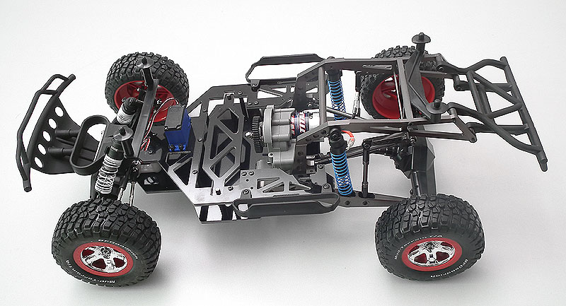
Вот тот самый донор:

А вот пара видео с этапами проекта:
Вот плейлист всех связанных с проектом видео:
www.youtube.com/playlist?list=PL9CNuWwXAbwWWyBOQul…
О будущих модификациях проекта буду сообщать по мере появления оных 😄
Спасибо за проявленный интерес!
P.S. Тема создается во второй раз и, скорее всего, в последний. На случай, если будет опять удалена, то сразу извините те, кому интересно, пересоздавать третий раз не буду 😃
Всем привет!
Погода на улице прям весенняя, а от сюда и возможность использовать подъезд для покраски кузова. 😃 Вот небольшое видео о том, что из этого получилось:
Всем привет!
Вчера, спустя полтора месяца после начала работы над проектом, провел первые полевые испытания 😃 И вот небольшой отчет.
Во-первых блокировка диффа в донорской трансмисси приказала долго жить на первых метрах езды 😃 в полевых условиях пришлось зажать хекс ключом с одной стороны выходящий из диффа вал. Это первое, над чем я буду работать в ближайшее время. Залью его чем-то, например, эпоксидкой или найду какой-то другой разборной способ.
Во-вторых после нескольких пробных кругов стало очевидно, что без стабилизатора это чудо сможет ехать только по прямой немного кренясь на бок при ускорении. Уж очень сильно кренится в повороте задница.
В остальном, шась показала себя крайне убедительно.
Вот небольшой фото-отчет:

А вот и небольшое видео:
Отчетливо видно необходимость стабилизатора и работу подвески 😃
Классно! А главное всё выглядит аккуратно и работает!
Стабилизатор однозначно нужен)
Отличный проект, качественная реализация! буду следить за апгрейдами:)
небольшое видео
Все круто, НО
- Стабы тебе нужны как минимум передние. С задними ты заколебешься их делать т.к. ни один стандартный не подойдет. Если тока от 1/8
- Подвеска на видео у тебя не работает ааще. Ты бы сделал там трамплинчик 5-7см и увидел бы разницу
- машина поворачивает тока при перегазовке в заносе т.к. у тебя заблокирован диф или просто потому что сносит жопу — эт не айс для лета 😃
- жопа меня кажется слишком легкая т.к. сносит машину слишком рано и слишком непредсказуемо
Проверь развесовку — по своему опыту должно быть не меньше 35/65 иначе поворачивает плохо. В идеале 30/70
Ждемс боевой видос 😃
- Стабы тебе нужны как минимум передние. С задними ты заколебешься их делать т.к. ни один стандартный не подойдет. Если тока от 1/8
Над стабилизатором ведутся работы, в первую очередь над задним, передний можно всегда прикрутить готовый.
- Подвеска на видео у тебя не работает ааще. Ты бы сделал там трамплинчик 5-7см и увидел бы разницу
Как закончу с кузовом и погода позволит, обязательно сделаю трамплины и прыжки! Мне для первого раза хватило информации для размышления, что мне делать дальше 😃
- машина поворачивает тока при перегазовке в заносе т.к. у тебя заблокирован диф или просто потому что сносит жопу — эт не айс для лета
На самом деле дифф там разблокирован. Повороты такие тугие потому, что было очевидно, что в более крутой поворот она не войдет, т.к. перевернется из-за отсутствия того же стабилизатора.
- жопа меня кажется слишком легкая т.к. сносит машину слишком рано и слишком непредсказуемо
Пока развесовка получается 55/45 (перед/зад) на осях.
Проверь развесовку — по своему опыту должно быть не меньше 35/65 иначе поворачивает плохо. В идеале 30/70
Спасибо за совет, но в моем случае это будет возможно только перемещением батареи куда-нибудь в опу 😃
На самом деле дифф там разблокирован.
Тоже от аксиала поставил диф? какой силикон залил? 😃
Пока развесовка получается 55/45
Эт жесть… Есть куда двинуть акк и мотор с регом? Кинь фотку вида сверху без корки
Тоже от аксиала поставил диф? какой силикон залил?
Дифф от аксиала, а внутренности от HPI (HPI86014, здесь две пары, т.ч. если сотрется, поставлю замену сразу). В коробке валяется локер, который был в комплекте с диффом, но я его пока че-та не хочу ставить, хотя слышал с ним тоже забавно ездит ) Ах да, силикон не заливал, т.к. мне что-то сразу в голову не пришло, как загерметить места вставки полуосей. Забил литолом все.
Эт жесть… Есть куда двинуть акк и мотор с регом? Кинь фотку вида сверху без корки
Не, мотор уже никуда не двинуть, регуль можно двинуть чуток ближе к заду, как он у меня и стоял изначально, но тогда он получается сбоку и тогда уже центр тяжести в бок смещается грамм на 150. Я думал, если будут проблемы с развесовкой, то взять купить батарейки, которые идут маленькие но парой, и всунуть их куда-то в заднюю часть рамы, там где спойлер. Фотку скину позже
внутренности от HPI
Это очень правильно! Там шайбочки, с которыми работает лучше.
В коробке валяется локер
Стоковая ГП хардкорного моста — унылое Г, как и все шестеренки от RC4WD… У меня стоит 36/14 аксиал — самая неубиваемая ГП!! Износа нет вааааще!!! )))

загерметить места вставки полуосей
Я мост буду перебирать и сфоткаю, нормально там все резинками зажимается, просто нужно из поджать шайбами.
силикон не заливал
Лучше залить погуще т.к. при поворотах диф будет недогруженное колесо разгонять и тачка поведет себя оч неприятно))
в заднюю часть рамы
Тут главное — чем ниже тем лучше!
Кинь фотку вида сверху без корки
Новую фотку сложно сделать, там сзади долго разбирать, вот одна из старых фоток:

Стоковая ГП хардкорного моста — унылое Г, как и все шестеренки от RC4WD… У меня стоит 36/14 аксиал — самая неубиваемая ГП!! Износа нет вааааще!!! )))
Да-да, $28, я тоже ее хочу заказать 😃 Ближе к лету это и сделаю. У меня, правда, не хардкордовский мост и дифф от аксиала, но и он сделан не пойми из чего.
Я мост буду перебирать и сфоткаю, нормально там все резинками зажимается, просто нужно из поджать шайбами.
Хочется посмотреть на фотки, но кажется я понял про резинки 😃 Спасибо за наводку!
Вот немного фоток по горячему…


там сзади долго разбирать
Да ты кузов сними просто и сфоткай…
одна из старых фоток
Ну у тебя 99% копия конверсии от РЦ4ВД и это совсем не айс изза развесовки… акк переносить на жопу опасно, он должен быть в базе
не хардкордовский мост
А какой? от врайта?
П.С. Тогда смысла сильно заморачиваться дальше не вижу т.к. это тупиковая шась — красивая но не для трассы и ломучая будет как ни усиливай, особенно на трампах. Просто поверь 😃
А какой? от врайта?
Там в первом видео есть фотка. Вот этот мост.
Тогда смысла сильно заморачиваться дальше не вижу т.к. это тупиковая шась — красивая но не для трассы и ломучая будет как ни усиливай, особенно на трампах. Просто поверь
Я бы не стал называть тупиковой шась, которой 2 месяца с момента зачатия, и тем более, которая изначально для башинга не предназначалась 😉 Я не поклонник одной модели на все случаи жизни, каждой модели — свое назначение. Что же касается трамплинов, будет видно на следующем тесте 😃
Ко всему прочему, прошли слухи, что RC4WD вместо хардкордного кита собирается делать что-то другое, которое должно быть гораздо круче. Может быть и мост сделаю какой-то клевый, я себе бы поставил что-то более подходящее 😃
Вот этот мост.
Ну норм тоже, хоть с полуосями проблем не будет как у меня, что замену не найти 😃
Я не поклонник одной модели
Вот эт правильно! Эт я маньяк хочу все и сразу 😃
прошли слухи, что RC4WD вместо хардкордного кита собирается делать что-то другое
Я в принципе не удивлен т.к. SCORE и GLAMIS за океаном дико популярны! И стоит это что-то будет полюбас дофига!!! А откуда слуха то?
что-то более подходящее
Моста круче и крепче Kyosho Mad Force / Kruiser еще не придумали 😒

Моста круче и крепче Kyosho Mad Force / Kruiser еще не придумали
Еще бы он выглядел по-человечески, тогда бы цены не было точно 😃 В моем случае, по-мимо ездовых характеристик, я хотел добиться и копийности и только хардкордный мост реально отвечает всем требованиям, мой от Axial’a все же не такой с виду клевый, хотя и плюс у него в том, что дифф обслуживать просто.
А вот немного о начале работ над задним стабилизатором:

Вот по ближе:

…и то, как оно гнется при сжатии одной стороны:

Вообще, это пока только набросок, т.к. крепление еще в пути, а жесткость найденной стали не такая, как мне хотелось. Поэтому пока я в поисках прутка с повышенной жесткостью от 2.5мм до 3мм, не знаю пока где найти. Видел, что кто-то использовал басс струну от пианино, но найти ее тоже не получается 😦
не знаю пока где найти.
возьми набор готовых стабов для 1/8… замучаешься сталь такую пружинную искать
Все конечно красиво…вот только я не понимаю зачем такая конструкция подвески что бы получить то что видно на видео…
Юра свой трофитрак то же делает, но он у него не едет мягко и стабильно как 1:1. И здесь походу подвеска только для вида и того что бы кренится в поворотах)))) Даже на мелких неровностях скачет чуть ли не больше чем стоковый слешик. Где работа энергоемкой подвески на неровностях?
Юра свой трофитрак то же делает, но он у него не едет мягко и стабильно как 1:1
А он у него с первого раза поехал мягко и стабильно, как 1:1? Даже ни разу нос вверх не задирал, даже не переворачивался? 😃 Не забывайте, проекту чуть больше месяца, шась 1 раз была на улице и вы ожидаете снгосшибательных результатов? Нет, увольте 😃 Только в волшебном и сказочном мире проекты работают так, как задумано без тестовых испытаний 😉
И здесь походу подвеска только для вида и того что бы кренится в поворотах))))
Рад, что вам понравилось 😃
А он у него с первого раза поехал мягко и стабильно, как 1:1? Даже ни разу нос вверх не задирал, даже не переворачивался?
Ну дык написано же “не едет”))))) Читайте внимательней.
Я на нем катнул, так он отрабатывает неровности хуже чем машинка на баггийных амортах с обычной стоковой подвеской.
шась 1 раз была на улице и вы ожидаете снгосшибательных результатов? Нет, увольте 😃 Только в волшебном и сказочном мире проекты работают так, как задумано без тестовых испытаний 😉
Да нет конечно. Сам тестирую неделями каждую фигульку. Просто когда пишут что шась в остальном показала себя убедительно…возникает вопрос в чем конкретно убедительно? Едет по относительно ровному грунту? Тогда зачем такая подвеска?
Рад, что вам понравилось 😃
Мне понравился кузов ну и внешний вид…а все что связано с необычной подвеской не то что бы не понравилось, но оно увы пока работает хуже обычной. Т.е. приобрела проблемы продольных рычагов но не получила их преимуществ. И походу все это в угоду дизайну?
возникает вопрос в чем конкретно убедительно?
В том, что виден потенциал. Если этого не видно на видео, то этому есть два объяснения, либо там это плохо показано, либо плохо смотрите. Мне, как владельцу, конечно, сложно оценить насколько можно ощутить эффект вождения по видео, когда есть фактический опыт. Тем не менее
Едет по относительно ровному грунту?
Даже на мелких неровностях скачет чуть ли не больше чем стоковый слешик.
Кстати о мелких неровностях и стоковом слеше:
Вот здесь (для упрощения задачи начало с 2:17)
едет фул сток platinum slash (4*4 правда) без тюнинга вообще, вот прям из коробке в поле.
Если все еще не видна разница, то суть моего теста по мелким неровностям была в том, чтобы понять, насколько эти неровности передаются самой раме и, в честности, корке. Если в случае со стоковым слешем, то корка там просто пляшет лезгинку, когда в первом же пробном заезде сфабрикованной шасси — она практически не меняет своего положения.
Тогда зачем такая подвеска?
Впереди весна, лето, время адекватных испытаний и тестов, и я думаю, что шась еще себя покажет 😉
шась еще себя покажет
Конечно покажет! Но не эта)))
У меня уже 4ая или даже 5ая версия всей машины и все равно зараза не едет как надо! Это процесс очень не быстрый )))
Конечно покажет! Но не эта)))
У меня уже 4ая или даже 5ая версия всей машины и все равно зараза не едет как надо! Это процесс очень не быстрый )))
Не в версиях дело и тем более не в их количестве…вы как то увлекаетесь больше внешним видом и мелочами а не настройкой подвески 😉
Я сколько раз тебе советовал заняться “мягкостью” амортов? и про то как их лучше поставить. А ты все версии…а в итоге машинка как табуретка скачет и по сей день.
Вот отработай подвеску как ЕДИНСТВЕННЫЙ необычный нюанс этих машин а потом уж ковырять дизайн.
Если этого не видно на видео, то этому есть два объяснения, либо там это плохо показано, либо плохо смотрите.
Ну видимо плохо смотрю…
вы как то увлекаетесь больше внешним видом и мелочами а не настройкой подвески
на самом деле, я жду не дождусь, когда будет подходящая погода, чтобы заняться отладкой подвески, к которой у меня лежит целый пакет тюнинга 😃
вот часть этого пакета:

А что еще остается делать, когда за окном 15-20 ниже нуля? 😃 Вот занимаюсь деталями, которые, кстати, входили в мои планы изначально, т.к. хотелось сделать не очередной шортоподный проект с одноцветной коркой.
Вот, кстати, в продолжение темы про детали свежачок: